
Project Overview
The purpose of this project was to build a circuit in multisim that can count up from 80 using a SSI and MSI counter in sequence. Also to create a reset switch to set at 0 at any point.
In PLD mode pins were assigned at all the inputs and outputs. They were also assigned to the grounds and powers. The inputs were all the things I had to add like the clock and switch. The outputs were everything that was visible like the LED's. To upload it you connect the computer to a chip then wire it based off what pins you used.
Final Project Conclusions
- Small Scale Integration uses less than 10 gates and Medium Scale Integration uses 10-100 gates.
- The limitations of the MSI circuit is it always counts up and starts at 0
- The "Ripple Effect" means there is a flickering of the display due to a signal delay
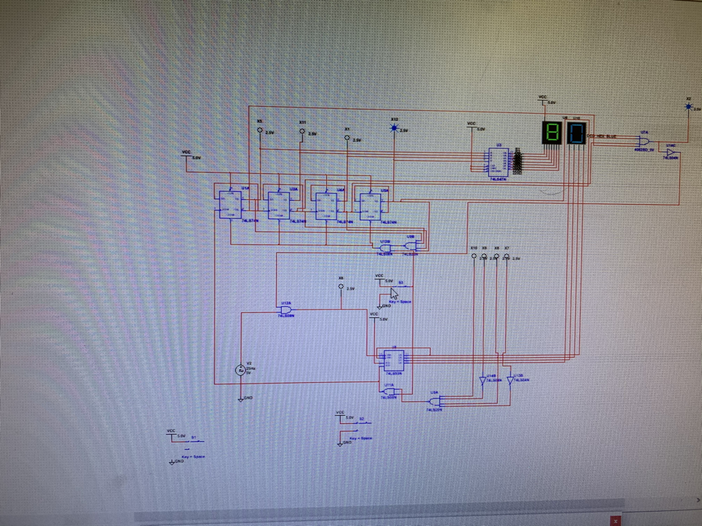
- When I start the simulation the clock sends a signal through the 74LS93 chip making it add 1 to the count. I was trying to detect a 10 with Q's (1) and not Q's (0) to show a 9. I connected a inverter to the lsb and third bit to detect a 10. Once a 10 is detected the nand gates detect it and sends a signal to the tens place counter which uses 74LS 74 chips to go up one. This continues all the way to 80 and then it is detected by a four input and gate going to an inverter gate. This goes to an and gate with the other input being the clock voltage. Then this is finally outputted to one of the inputs in the 74LS93 chip stopping the count. The reset switch when switched sends a 0 signal to both the tens and ones counter. It can be sent to 0 at any time. For the ones counter the 0 signal goes through a nand gate along with a 1 signal which makes the output 1 go to the reset on the 74LS93 chip. For the tens counter the 0 signal goes into an and gate along with a 1 signal from the circuit. That makes the output 0 go into the clears of the 74LS74 chips making them reset to a 0.
- Anthony's circuit was very different than everyone else because he used transistors for his pause button instead of normal logic.
