Project Overview

The purpose of the circuit in this project is to be an electronic voting system that can show if the vote of the four board members (the president, the vice president, the secretary, and treasurer) is a yes or no. The circuit that we created has the constraints of only using two-input gates. Also the circuit has to be designed so that in a case of a tie, the president's vote will be the tie breaker. This final report of the circuit will show if the decision passed or didn't pass.
Problem Conception

The truth table shows all the different possible combinations with the board members. It also shows what the output of each combination would be. The number of rows is equal to 2 raised to the fourth power because there are four variables in the circuit. If there is a tie in the table whichever side the president is on wins the vote.
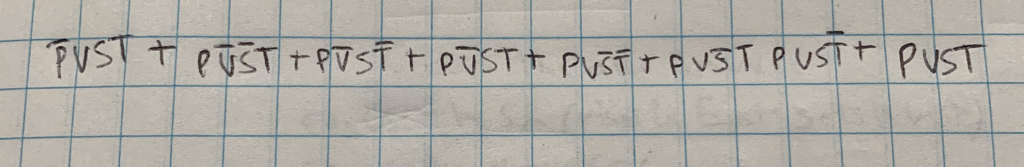
The un-simplified logic expression came from every combination on the truth table that gave a 1 as the output. This expression is in SOP form. Each minterm comes from the combination of every row that had a 1 in the decision column. I have my expression in SOP form because it is easier to read and get it from the table.
Un-simplified circuit

My un-simplified circuit is in the bus form to make it easier to manage and read. I needed 24 AND gates, 4 Inverter gates, and 7 OR gates. For the un-simplified circuit you would need 9 chips in the breadboard for all the gates.
Boolean Algebra Simplification
The Boolean algebra is simplifying the un-simplified circuit to a simplified version that makes it easier to read and breadboard.


Simplified Circuit

In the simplified circuit I used bus form. I did this because it makes it neater and easier to read. I didn't use a resistor in my schematic of the simplified circuit. The resistor would of been helpful by restricting some of the energy from flowing through so that the LED doesn't burn. In this circuit I didn't need any inverter gates. I needed 3 OR gates and 5 AND gates for a total of 8 gates in my circuit. For that amount of gates I needed 2 74LS08 (AND gate) chips because every chip has four gates and I needed 5 gates for my circuit. I also needed one 74LS32 (OR gate) chip because I only needed 3 gates.
This circuit contained a lot fewer gates and chips. The simplified circuit contained only 8 gates which is 27 less gates than the 35 gates in the un- simplified version. The simplified circuit also contained 6 less chips than the un-simplified circuit contained. It is imporntant to simplify the un-simplified circuit because it makes bread boarding and creating the circuit a lot faster and easier. Also it is a lot less wiring to do, which means less mistakes you can make, and wiring the un-simplified circuit would be very hard and take forever.
This circuit contained a lot fewer gates and chips. The simplified circuit contained only 8 gates which is 27 less gates than the 35 gates in the un- simplified version. The simplified circuit also contained 6 less chips than the un-simplified circuit contained. It is imporntant to simplify the un-simplified circuit because it makes bread boarding and creating the circuit a lot faster and easier. Also it is a lot less wiring to do, which means less mistakes you can make, and wiring the un-simplified circuit would be very hard and take forever.
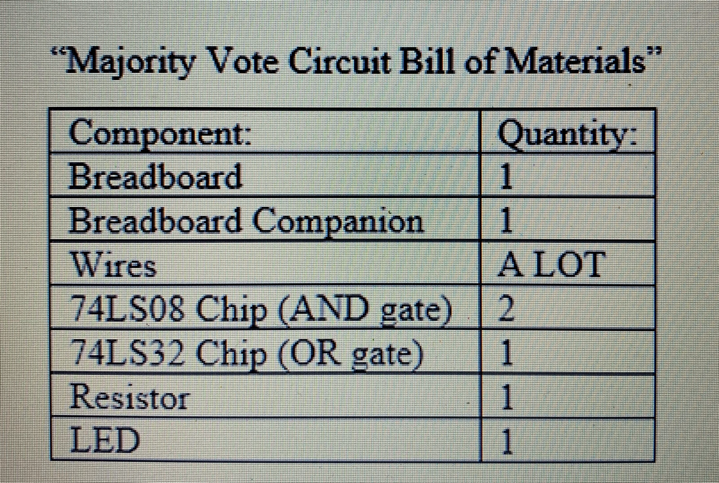
Bill of Materials
This is a table of all the materials and the quantity of each that went into my circuit.
Bread-boarding

This is an image of me just starting breadboarding the circuit. All I have added is the breadboard companion.

This is an image of my circuit halfway done. I have added all the chips and started to wire my circuit.

This is an image of me working on my finished circuit. This is when I just finished wiring and fixed my mistakes.
My first breadboarding experience went pretty well. I thought it was going to go horrible but Mrs. Zienty walked us through it and when I was done my circuit was working. This was a lot different then breadboarding this circuit. I made a lot of minor mistakes that affected my circuit in huge ways. I learned that the best way to breadboard is to look at your circuit on Multisim. This was one of the reasons I had so many mistakes. I had to do a lot of troubleshooting to make my circuit work. I had to rewire the OR gate because I had only used 2 gates instead of 3. Also I checked every wire to see if everything was in the right place. I finally had to ask Mrs. Zienty for help and she showed me that in my second AND gate I had to shift all my wires one over. Then my circuit was working perfectly.
Final Project Conclusions
One important takeaway from this project is take your time and check everything. If I took my time and double checked all my wires I would of finished a lot faster giving me more time to do the weebly. Another important takeaway is focus on yourself. While I was breadboarding I kept looking at other people’s circuits and tried to do what they were doing. What I should’ve done is focus on my own circuit and look at multisim. I would of finished faster and it would of probably worked. This project shows that all it takes is time and perseverance to accomplish something. If you keep working at something and don’t give up you are destined to do it one day. The first step in the process from going from a problem statement to a finished circuit design is the truth table. Then using the truth table you create the un-simplified expression. Then you create the un-simplified circuit. After that you use Boolean algebra to create the simplified expression. You then create the simplified circuit. Finally after that you breadboard and create your final circuit design. Boolean Algebra is useful in simplifying expressions to make them easier to read, create a circuit, and Breadboard. This is my thought on the Majority Vote Project.
